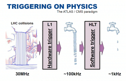
The image above was taken from Anna Sfyrla's 2017 summer student lectures, and illustrates the "crucial component of the experiment, responsible for selecting events of interest at a recording rate of approximately 1 kHz from up to 40 MHz of collisions". It features the Run2 architecture where the HLT - which @Run1 consisted in two separate Level-2 and Event-Filter - was merged into one single homogeneous farm.
Event selection has from the beginning been based on the presence of energetic leptons, photons, jets or large missing energy. But the trigger system is continuously improving and, despite the limited processing time available, it is now able to exploit topological information as well as multivariate methods, for example b-tagging or tau identification. The trigger composition and thresholds are optimised for several luminosity ranges, up to 2 1034 in 2018. A trigger menu specifies which triggers are used, how much rate each of them is allocated and the corresponding prescale sets get activated as the LHC instantaneous luminosity decreases.
See chapter 7.2 of the almost-ready ATLAS 25 book :
- the 3 key concepts are: start with a regional reconstruction ("Regions of Interest"), early rejection (as soon as each criteria is not fulfilled), fast algorithms (refined later).
- Run 1: ~400 trigger menus, 200-400 Hz. 3.6 109 events recorded
- Run 2: ~2000 trigger menus, 1-2 kHz. 12.6 109 events recorded up to 2017 [ number to be updated at the end of 2018 ]
Run 2 design facts and figures [ taken from the 2017 paper and a CHEP 2018 poster ]
L1 is implemented in hardware: uses a subset of the detector information to reduce the rate to 100kHz - Fixed latency of 2.5 micro-seconds
- L1 Calorimeter: the electron/photon/tau-lepton trigger algorithms look for isolated energy clusters in "trigger towers", apply calibration constants and transmit the energy & location of identified objects to HLT. For run 2, the corrections applied were refined: e.g. the pedestal substraction takes into account the LHC instantaneous luminosity to mitigate the effect of the pileup.
- L1 Muon: during LS1 additional chambers were added in "difficult regions", e.g close to the feet that support the ATLAS detector. The contribution of fakes and particle not originating from the interaction point was reduced by new coincidence requirements.
- Tracking is not currently used at L1 because reconstruction takes too much time. A new Fast Tracker system (FTK) is being tested, which will provide ID tracks by using lookup tables stored in custom memory chips, and a simplified linear fit. It will be in place for Run 3.
L1 Central Trigger Processor (CTP)
Due to the increased beam energy, Run 2 trigger rates would be in average 2 to 2.5 times larger than @Run1 for a given luminosity. Given the luminosity increase factors up to 5 were expect. Maintaining the single-electron and single-muon trigger thresholds to 25 GeV was essential to insure the collection of leptonic Z and W decays, which are crucial to study electro-weak processes. Several upgrades and additions were thus implemented during LS1:
- The L1 output rate was increased from 70 to 100 kHz. For this, some detectors had to modify their front end electronics and Readout (Muon system, Silicon Tracker), others reduce redundancy (LAr calorimeter). The data collection network and storage systems were fully replaced and upgraded.
- A new topological trigger (L1 Topo, commissionned in 2016) combines signatures from Calo and Muon. Rates are greatly reduced by using angular discances, di-objects masses, transverse masses, and global event variables such as missing transverse momentum.
- Higher luminosity means higher fake rates, but also higher detector occupancies. The CTP was upgraded to be able to address better sub-detector specific dead-times, noise and pileup substraction.
HLT is a software trigger: refered to a "online reconstruction", it runs @P1 on 40-50 k processing units. Average latency ~ 400 ms
Like in Run 1, HLT reconstruction can either be executed on the L1 Regions of Interest (RoI) or a full Event Building (EB). The new HLT farm architecture allows more flexibility than the previous L2 - EF split, and benefits from the offline algorithms CPU re-optimisation (e.g. for clustering in the calorimeters).
- Multi-stage reconstruction: most of the ~2000 active chains use a two stage approach: a fast pass to reject most of the events, and a slower precision reconstruction. A multi-stage tracking is used, in particular, for hadronic tau and b-jet triggers. For muons, the HLT includes MDT information to the L1 candidates in two steps, fast and precision. Same for electron and photon candidates, from a quick pass on L1 RoI to offline-like calibration and algorithms.
- Processing time per event: went up to 235 ms in 2015, constantly improved since (e.g 20% gain in the 2016-2017 technical stop). An L1 rate of ~80 kHz utilises 2/3 of a farm with 28 k CPU cores. About 40% of the HLT CPU is spent on tracking, 30% on muon spectrometer (maily low Pt B-physics triggers), 15% on calorimeters.
Online farm: its capacity is regularly upgraded to cope with the LHC performances. It included, in Dec 2016 [ CHEP 2016 talks on ATLAS Run2 TDAQ architecture and online system administration ]
- ∼4000 servers processing the data read out from ∼100 million detector channels through multiple trigger levels.
- a buffer capacity of 340 TB, which corresponds to 24h of ATLAS data.
In 2017 all detectors, Trigger and DAQ ran under stress, due to an unexpectedly high pileup, and ATLAS could handle a maximum pileup of ~60 and 80 KHz L1 rate. 20% more CPU was added in 2018 [ see LHCC open session reports Nov 2017 (slide 4) and May 2018 (slide 5) ]
Streams
Primary triggers cover all signatures relevant to the ATLAS physics program. As shown explicitely in their names (e.g. L1_2MU4; HLT_mu40), for each requested particle type (mu, electron, gamma, jet) a multiplicity and transverse momentum threshold are defined. Further identification criteria may be added (e.g. loose).
- Events accepted are written into ~20 separate data streams. The "express stream" is used to provide calibration and data quality information prior to the reconstruction of the full "main stream", which is typicaly processed 36 hours after data are taken.
- "End of fill triggers" are enabled after few hours of collisions, when the LHC luminosity has decreased enough to afford CPU intensive topologies (QCD multijet, B-physics, BSM signals with large QCD background). If data storage limitations are an issue for specialized streams, only a subset of the information is stored. One example is the di-jet resonance search [ CERN courrier article, 01.06.2018 ]
- "Delayed streams" are stored and reconstructed outside data taking periods ( which is ~ 2/3 of the year ), in parallel with simulation and data reprocessing.
Run 2 achievements [ see June 2018 Public note and ICHEP 2018 talk ]
2017 saw a significant increase of the luminosity, which lead to new optimisations but also alternative solutions such has partial event building and delayed streams. The L1 topological trigger proved to be a crutial component for maintaiing the ability to trigger on low momentum signatures with luminosities of 1.7 1034 cm-2s-1 ( up to 2 1034 at the end of the year). In 2018 (and thus all of Run 2) the Pt thresholds could be maintained and the main physics channels remained unscaled. New triggers were added to target previously uncovered phase space, for BSM searches in particular, and special attention was given to the channels sensitive to pile-up conditions.
Future challenges and technical developments [ TDAQ upgrade talks @ LHCP 2018 and CHEP 2018 ]
- Tracking: the development and integration of a Tracking based trigger component is essential to reduce rates and keep the single lepton triggers thresholds intact in Run 3 (expected luminosity of ~ 2.5 1034 @14 TeV) and LHC High-Lumi ( ~ 5 to 7 1034 and <mu> ~ 200 ). It will happen in two steps: software for Run 3 (FTK trigger) and then hardware for HL ( HTT = "hardware trigger for tracking").
- Rates & latency: the single hardware trigger (which will be called L0) will have a longer latency ( ~ 10 micro-second ) and may evolve - for some detectors - into 2 levels. All output rates (L0 accept, HLT accept, SFO output) will be multiplied by 10. An intensive software development program aims at reducing the CPU needs by using new specialised processors (FPGAs, GPUs). Larger event size are expected, due to pile-up but also sub-detectors inhanced grannularity.
- Sub-detectors: front-end electronics needs to be redone to prevent the dead time and saturation induced by higher rates, store data longer while waiting for the trigger decision and make use of recent radiation-hard technologies. These plans are detailed in the Technical Design Reports (TDR) which became mature, approved and public around 2018. Demonstrators are underway and production is expected to start ~ 2020
- HLT farm: the current estimate of the capacity needed is 4.5 MHS06 ( 1 current CPU core = 10 HS06 ), with 3000 servers in 38 racks. The speed at which modern system administration tools can fill, pause, drain such cluster is being studied. More generally, the Phase II upgrade will be an occasion to re-design the underlying network, racks layout and infrastructure.
- Manpower: the TDAQ Phase II Upgrade TDR provides estimates of the manpower needs. It quotes ~ 700 FTE in total, spread over 2018-2016. 40% scientists, 40% engeneers, 20% students from 20 contributing countries plus - of course - CERN.
Stories, images and videos
WARNING: both ATLAS public web site Trigger-DAQ description and 2012 Fact Sheet refer to the Run 1 trigger (which had 3 levels) and numbers obsolete ! Some fixing suggestions and links are collected in the file attached below.
- ATLAS news & blogs: all Trigger-DAQ related ATLAS updates are here
- Photos: of racks and electronics components via the public multimedia resources, of the HTL farm @P1 here
- CERN communication: very few articles can be found in the CERN courier and EP department news letter
- ATLAS insiders: can find recorded introductions in the Induction Days programs: e.g September 2017 (Joerg Stelzer) and January 2018 (Stefania Xella)
How much of it can we see @P1 ?
- Visitor center: there is a slide about trigger in the smartboard "complete" collection, but not up-to-date (see comments in the "fixing suggestions" file below)
- Control room view: the L1, HLT and recording rates are projected on the wall, usually on the left of the LHC page 1 and in front of the TDAQ and Trigger shifter desks (photo). The details are not meant to be public, but one can discuss the shifter's role and global shapes
- On the way down: the HLT online farm & TDAQ control room are located in "SDX1", which is a specific building behind (and above) the MAD/PAD area. See photos in the file attached. below. Access is protected, but a picture of the farm was used on the TDAQ Phase II Upgrade TDR cover page (screenshot attached below)
- Level -1: the L1 trigger and DAQ racks are in USA15 but not visible (curious ATLAS insiders may check where they are through the infrastructure -> counting rooms menus of the ATLAS detector operation page). The racks visible through windows while exiting the lift at -1 are actually Tiles (left side) and MDT (right side) electronics. But most guides do not go into details and stop there to discuss event building, event selection and data "shipping to the T0, the grid and the world".
Latest edition of this page: August 2018